Project Description


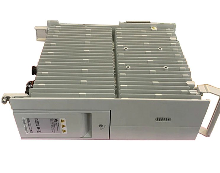
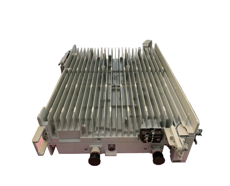
Brand new Huawei radio RRU5909 B1 B3 B8
Huawei Base station RRU5909 series Multi-mode(2*60w) B1 B3 B8
PN: 02311TBD, 02311PPP, 02311TAY
| Huawei | 02311TAY | RRU5909 – 900Mhz |
| Huawei | 02311PPP | RRU5909 – 1800Mhz |
| Huawei | 02311TBD | RRU5909 – 2100Mhz |
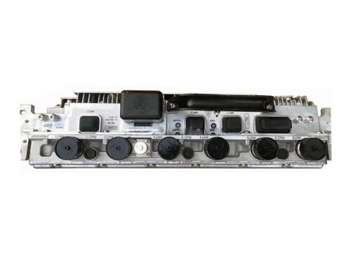
| Port | Connector | Quantity | Description |
| RF port | 4.3-10 connector | 2 | Connects to the antenna system. |
| CPRI port | DLC connector | 2 | Connects to a BBU. |
| Power supply port | Tool-less female connector (pressfit type) | 1 | Supplies–48 V power. |
| RET port | DB9 connector | 1 | Connects to a remote control unit (RCU). |
Frequency Band
| Module | Frequency
Band (MHz) |
RX Frequency
Band (MHz) |
TX Frequency
Band (MHz) |
IBW (MHz) |
| RRU5909 | 900 EGSM | 880 to 915 | 925 to 960 | 35 |
| 900 PGSM | 890 to 915 | 935 to 960 | 25 | |
| 1800 | 1710 to 1785 | 1805 to 1880 | 45 | |
| 2100 | 1920 to 1980 | 2110 to 2170 | 60 |
Capacity
| Mode | Capacity |
| GSM | (Supported only by the 900 MHz/1800 MHz frequency band) Each RRU5909 supports 8 TRXs. |
| UMTS | (Supported only by the 900 MHz/2100 MHz frequency band) Each RRU5909 supports:
•6 carriers without MIMO •4 carriers with MIMO |
| LTE | Each RRU5909 supports 2 carriers and the LTE bandwidth can be 1.4 MHz, 3 MHz, 5 MHz, 10 MHz, 15 MHz, or 20 MHz. |
Power Consumption
The typical power consumption and the maximum power consumption are measured when the ambient temperature is 25°C.
The typical power consumption for GSM is measured when the load is 30%. The maximum power consumption for GSM is
measured when the load is 100%.
The typical power consumption for UMTS is measured when the load is 40%. The maximum power consumption for UMTS
is measured when the load is 100%.
The typical power consumption for LTE is measured when the load is 50%. The maximum power consumption for LTE is
measured when the load is 100%.
This section describes the power consumption of an entire base station. Board configurations in a BBU are as follows:
GSM: One GTMU board
UMTS: one UMPTb1 and one WBBPf3 boards in 3×1 and 3×2 scenarios; one UMPTb1 and two WBBPf3 boards in 3×3
and 3×4 scenarios
LTE FDD: one UMPTb1 and one LBBPd1 board when one carrier is configured
Typical Output Power
An RRU5909 working in GSM mode and operating in the 900 MHz, 1800 MHz, or 2100 MHz frequency band complies with
the EN 301 502 V9.2.1 standard. An RRU5909 working in UMTS, LTE FDD, or MSR mode and operating in the 900MHz,
1800MHz, or 2100 MHz frequency band complies with the ETSI EN 301 908 V5.2.1 and 3GPP TS 37.104 standards.
For the RRU5909 working in GSM mode, the maximum output power per carrier is 60 W when the S1 or S2 configuration
is used. If the output power of 60 W is required, the corresponding power license must be purchased.
If an RRU5909 is located at an altitude of 3500 to 4500 meters, its power is reduced by 1 dB. If an RRU5909 is located at
an altitude of 4500 to 6000 meters, its power is reduced by 2 dB.
Factors such as the inter-site distance, frequency reuse factor, power control algorithm, and traffic model affect the gains
of dynamic power sharing. In most cases, network plans are designed based on the power specifications allocated by dynamic
power sharing.
Your Content Goes Here